𐄀 Technology Connection to Future
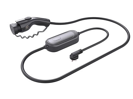


011.webp "Portable")
1. Superior Protection: Charging gun IP67, control box IP67, exceeding industry standards.
2. High Durability: 30,000 live plug cycles, 10,000 mud/saltwater cycles.
3. Lightweight: 20% fewer parts, 10% lighter than the previous generation.
4. Cost-Effective: 30% price reduction from the previous generation.
5. Sleek Design: Rock Gray // Galaxy Array // Angular Design for a modern look and comfortable grip.
6. Compact Size: Charging gun 15% smaller, control box 10% smaller than similar products.
7. Ergonomic: Smooth lines, comfortable grip for better handling.
· Model: YG196-535
· Rating: 16A, 220V @ AC 50Hz
· Rated Residual Operating Current: ≥25mA ±5mA
· Residual Non-Operating Current: <25mA ±5mA
· Protection Level: IP67
1. Temperature: -30℃ to +50℃
2. Altitude: ≤4000m
3. Max Relative Humidity (at 40℃): 75%
4. External Magnetic Field: ≤5× Earth's geomagnetic field in any direction
5. Max Daily Average Temperature: +35℃
6. **Avoid use near strong magnetic fields
7. Storage & Transport: -40℃ to +85℃
If the fault indicator remains on or flashing, refer to the LED fault guide for diagnosis. Check the user manual for troubleshooting. If the issue persists, contact your local dealer.
After a residual current trip, unplug and reinsert the three-prong plug to reset.
1. Before charging, turn off the vehicle’s power system, shift to Park (P), and engage the parking brake.
2. Open the protective cover of the vehicle’s AC charging socket.
3. Remove the charging gun from its storage.
4. Insert the three-prong plug into the power outlet.
5. Remove the protective cover from the vehicle connector.
6. Press the locking clip button, insert the connector vertically into the vehicle’s AC charging socket until fully engaged, then release the button.
7. Start charging according to the vehicle’s instructions.
8. After charging, wait for the charging process to stop, then press the locking clip button and unplug the charging gun vertically.
9. Unplug the three-prong plug from the power outlet, organize the cable, and store the charging gun properly.
10. Close the socket cover as per the vehicle's instructions to complete the process.
1. Keep the protective cover on the vehicle connector when not in use.
2. After charging, neatly store the product in its storage bag or designated vehicle compartment.
3. Store in a dry, clean area, away from fire sources and moisture.
The indicator light status on the in-cable control box is shown in Table 10.
Table 10 Indicator lights on the cable control box
No. | Function Status | LED Indicator (LED1,LED2,LED3,LED4) | Description | Remarks |
LED indicator | Red, Green, Yellow, White,Blue | |||
1 | Initial State | White blinks once | Initialization | Power-on self-check |
2 | Waiting for Connection | White steady | CP voltage 12±0.8V, relay open | |
3 | Self-check Failure | Red fast flashing | ||
4 | Ready to Charge | Blue steady | CP voltage 9±0.8V, relay open | |
5 | Charging | Green slow flashing | CP voltage 6±0.8V, relay closed | Relay activated |
6 | Charging Completed | Green steady | CP voltage changes from 6±0.8V to 9±0.8V (no fault) | Relay transitions from closed to open |
7 | Over-temperature | Yellow steady | CP voltage changes from 6±0.8V to 9±0.8V (no fault) | Relay disconnected |
8 | Input Not Grounded | Yellow fast flashing | Charging allowed; indicator signals grounding issue; power cycling can restore | Relay closed |
9 | Ground Fault During Charging | Yellow and green alternate slow flash (1s interval) | Charging allowed; indicator signals grounding issue; power cycling can restore | Relay closed |
10 | Weak Overcurrent | Red and blue slow flashing (1s interval) | Overcurrent protection alarm | Relay disconnected after three occurrences |
11 | Strong Overcurrent | Red and blue fast flashing | Overcurrent protection alarm | Relay disconnected; power cycling can restore |
12 | Leakage Current | Red slow flashing (1s interval) | Leakage current 25mA±5mA | Relay disconnected |
13 | Communication Failure | Yellow slow flashing (1s interval) | CP fault alarm | Relay disconnected |
14 | Relay Sticking | Red steady | Detected before and after relay closure, triggers alarm | |
| 15 | AC Over/Under Voltage | Overvoltage: Red & Yellow slow flashing (1s interval) Under-voltage: Red & Yellow fast flashing | AC overvoltage 264±5V, AC undervoltage 90±5V | Relay disconnected |
The LED indicator control priority is shown in Table 11 below:
No. | Fault Status | Priority |
1 | Leakage Current | 1 (Highest) |
2 | Over-temperature | 2 |
3 | Communication Failure | 3 |
4 | Overcurrent | 4 |
5 | Over/Undervoltage | 5 |
6 | Poor Grounding | 6 (Lowest) |
1. Use a 16A power outlet for charging.
2. Do not use extension cords, grounding adapters, converters, or any accessories not part of the IC-CPD, unless specified.
3. Do not short-circuit the neutral or live wire with the ground wire.
4. Use a socket that has good contact with the plug. If loose, replace it immediately.
5. Only use in environments where the power supply has a leakage protection device.
6. Do not charge if the charging cable is damaged.
7. Keep the plug and socket dry—avoid rain or moisture.
8. If the plug/socket has dirt or foreign objects, clean it before charging.
9. Do not disassemble the product—it contains no user-serviceable parts.
10. Do not touch the charging port while charging.
11. Do not forcibly remove the vehicle plug during charging.
12. Do not start the vehicle while the plug is still connected.
13. Always pull out the charging plug straight—do not tilt or shake it.
14. Combination-type IC-CPD is allowed, but all accessories must be from the original manufacturer and serviced by the manufacturer if damaged.

Tailoring connectors to your unique needs.
Provide systemic solutions
Respond to needs within 12 hours


 English
  日本語
日本語  Deutsch
  ไทย
ไทย  русский
  العربية


