𐄀 Technology Connection to Future


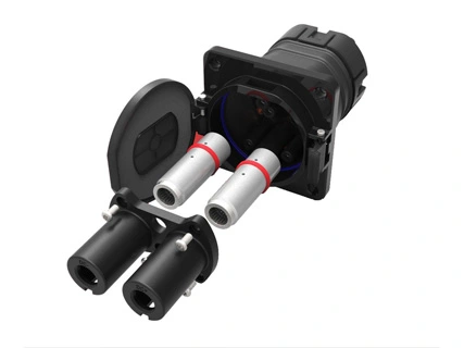
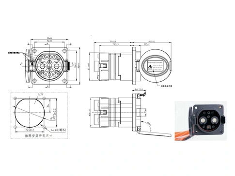
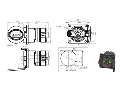
Vehicle inlet (front-mounted, Flip-top type, right flip-top)
Technical parameters | |||||||||||
Electrical parameters | Port definition | DC± | PE | A± | CC1 | CC2 | S± | ||||
Wiring specification (unit: mm2) | 25 | 35 | 50 | 70 | 70 | 0.75~4 | 0.75 | 0.75 | 0.75 | ||
Contact Terminal Diameter (mm) | Φ12 | Φ6 | Φ3 | Φ3 | Φ3 | Φ3 | |||||
Rated Operating Voltage (DC) | 750V/1000V | / | 0~30V | 0~30V | 0~30V | 0~30V | |||||
Rated Operating Current (DC) | 80 | 125 | 200 | 200 | 250 | 2~20A | 2A | 2A | 2A | ||
Contact resistance | ≤0.3mΩ | ≤0.4mΩ | ≤3mΩ | ||||||||
Insulation resistance | ≥2000MΩ(1000V AC) | ||||||||||
Pressure withstand (50Hz, AC Normal) | Test after plug wiring: ① Resistance voltage between DC + and DC-3500V AC 1min; ② DC +, DC-and PE, S +, S +, A +, A-resistance voltage 1500V AC 1min; ③ PE and S +, S-, A +, A-respectively resistant voltage 1500V AC 1min; ④ S +, S-, CC1, A +, A-two resistance voltage of 1500V AC 1min; Test after the receptacle is wired: ① Resistance voltage between DC + and DC-3500V AC 1min; ② DC +, DC-and PE, S +, S-, CC1, CC2, A +, A-resistance voltage 1500V AC 1min; ③ PE and S +, S-, CC2, A +, A-resistance voltage 1500V AC 1min; ④ S +, S-, CC2, CC1, A +, A-two mutual voltage resistance of 1500V AC 1min | ||||||||||
Mechanical performance parameters | Service life: | 10000 times | |||||||||
| Plug and pull force: | 140N | ||||||||||
| Lock-in force: | 200N | ||||||||||
Environmental performance parameters | Before insertion: | IP54 | |||||||||
After insertion: | IP55 (head, seat connection position) IP67 (tail of receptacle, please pay attention to avoid tail wiring bending radius <6x cable OD) | ||||||||||
Ambient temperature: | -30℃ ~ + 50℃ | ||||||||||
Materials | Housing: | Engineering plastics (temperature resistant PA66 or temperature resistant PC) | |||||||||
Terminal: | copper, surface silver-plated | ||||||||||
Seals: | silicone rubber or elastic | ||||||||||
Flame retardant grade of insulation materials: | UL94 V-0 | ||||||||||
Implementation standards | GB / T 18487.1-2015 EVs-Part 1: | General Requirements | |||||||||
GB / T 20234.1-2015 Connecdevices for conductive charging of electric vehicles-Part 1: | General Requirements | ||||||||||
GB / T 20234.3-2015 Connections for Electric Vehicle-Part 3: | DC Charging Interface | ||||||||||
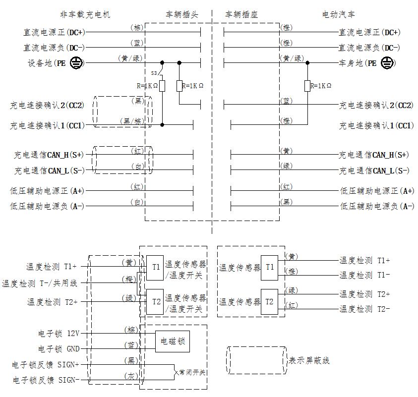
Electrical principle | |||||||||||
Function definition of each terminal | No. | Terminal identification | function definition | ||||||||
| 1 | DC+ | The DC power supply is positive, and the connected DC power supply is facing the battery cathode | |||||||||
| 2 | DC- | The DC power is negative, connect the DC power is negative and the battery is negative | |||||||||
| 3 | PE | Protective ground (PE), connect to the ground wire of the power supply equipment and the vehicle body ground wire | |||||||||
| 4 | S+ | Charging communication CAN _ H, connecting the communication line between non-on-board charger and electric vehicle | |||||||||
| 5 | S- | Charging communication CAN _ L, connecting the communication line between the non-on-board charger and the electric vehicle | |||||||||
| 6 | CC1 | Charging connection confirmation 1 | |||||||||
| 7 | CC2 | Charging connection confirmation 2 | |||||||||
| 8 | A+ | The low voltage auxiliary power supply is connected to the low voltage auxiliary power supply provided by the non-on-board charger for electric vehicles | |||||||||
| 9 | A- | Low voltage auxiliary power supply is negative, connected to the low voltage auxiliary power supply provided by non-on-board charger for electric vehicles | |||||||||
| 10 | T1+ | The temperature sensor is positive on the right side of the DC power supply | |||||||||
| 11 | T1- | The temperature sensor of the DC side is negative | |||||||||
| 12 | T2+ | The negative-side temperature sensor of the DC power supply is positive | |||||||||
| 13 | T2- | The temperature sensor is negative on the negative side | |||||||||
★ T1-and T2-are available | |||||||||||
Electrical schematic diagram: |  | ||||||||||
Supporting accessories | |||||||||||
NTC/PT Temperature sensor size |
★ Note: ①②③ is the required size, the rest of the dimensions can be customized ★ Recommended MT20.NTC01.L382 200 thermal temperature sensor (501021702657) with 4 temperature point resistance values as follows:
★ Recommended MT20 PT1000A LA380 200 PT1000 temperature sensor (501021702658), the 4 temperature point resistance values are as follows:
★ See the specifications of the above sensor performance; ★ According to the standard, select two sensors in DC + / DC-, and order with the receptacle, order ratio 1:2 (receptacle: temperature sensor). | ||||||||||
Notes for use | |||||||||||
| Attached announcement information: | explain: ★ The announcement logo corresponds to the model table "name" | ||||||||||
Announcement logo | Temperature control device | Strong inspection report number | CQC report number | ||||||||
YGC1201-EV-S9RA-250 | have | QA19EE1XB7261 QA19EG1XB7261 | |||||||||
YGC1201-EV-S9RB-250 | have | QA19EE1XB7261 QA19EG1XB7261 | |||||||||
YGC1201-EV-S9RA/1-200 | have | QA19EE1XB7261 QA19EG1XB7261 | |||||||||
YGC1201-EV-S9RB/1-200 | have | QA19EE1XB7261 QA19EG1XB7261 | |||||||||
YGC1201-EV-S9RA-125 | have | QA19EE1XB7261 QA19EG1XB7261 | |||||||||
YGC1201-EV-S9RB-125 | have | QA19EE1XB7261 QA19EG1XB7261 | |||||||||
YGC1201-EV-S9RA-80 | have | QA19EE1XB7261 QA19EG1XB7261 | |||||||||
YGC1201-EV-S9RB-80 | have | QA19EE1XB7261 QA19EG1XB7261 | |||||||||
YGC1201-EV-S9RA-200 | have | QA19EE1XB7261 QA19EG1XB7261 | |||||||||
YGC1201-EV-S9RB-200 | have | QA19EE1XB7261 QA19EG1XB7261 | |||||||||

Tailoring connectors to your unique needs.
Provide systemic solutions
Respond to needs within 12 hours