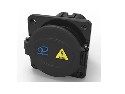
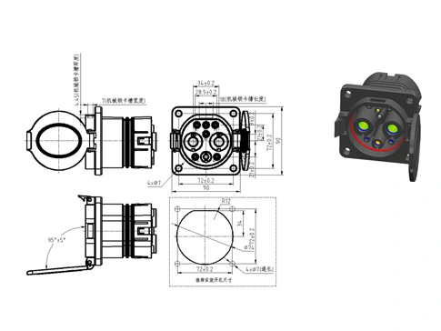
𐄀 Technology Connection to Future


Technical parameters | ||||||||||
Electrical parameters | Port definition | DC± | PE | A± | CC1 | CC2 | S± | |||
Wiring specification (unit: mm2) | 25 | 35 | 50 | 70 | 25 | 0.75~4 | 0.75 | 0.75 | 0.75 | |
Contact Terminal Diameter (mm) | Φ12 | Φ6 | Φ3 | Φ3 | Φ3 | Φ3 | ||||
Rated Operating Voltage (DC) | 750V/1000V | / | 0~30V | 0~30V | 0~30V | 0~30V | ||||
Rated Operating current (DC) | 80A | 125A | 200A | 250A | / | 2~20A | 2A | 2A | 2A | |
Contact resistance | ≤0.3mΩ | ≤0.4mΩ | ≤3mΩ | |||||||
Insulation resistance | The insulation resistance between any adjacent contact pair and between any contact pair and the enclosure shall be 2000 MΩ, test voltage DC 1000V± 50V; (no required between CC1 and PE) | |||||||||
Pressure withstand (50Hz, AC normal) | Test after the receptacle is wired: ① Resistance voltage between DC + and DC-3000V AC 1min; ② DC +, DC-and PE, S +, S-, CC1, CC2, A +, A-resistance voltage 1500V AC 1min; ③ PE and S +, S-, CC2, A +, A-resistance voltage 1500V AC 1min; ④ S +, S-, CC2, CC1, A +, A-two mutual voltage resistance of 1500V AC 1min | |||||||||
Mechanical performance parameters | Service life: | 10000 times | ||||||||
| Plug and pull force: | 140N | |||||||||
| Lock-in force: | 200N | |||||||||
Environmental performance parameters | Before insertion: | IP54 | ||||||||
| After insertion: | IP55 (head, seat connection position) IP67 (tail of receptacle, please pay attention to avoid tail wiring bending radius <6x cable OD) | |||||||||
| Ambient temperature: | -30℃ ~ + 50℃ | |||||||||
| Temperature rise: | 50K | |||||||||
Materials | Housing: | Engineering plastics (temperature resistant PA66 or temperature resistant PC) | ||||||||
| Terminal: | copper | |||||||||
| Seals: | silicone rubber or elastic | |||||||||
| Flame retardant grade of insulation materials: | UL94 V-0 | |||||||||
Environmental protection: | meet the ROHS 2.0 | |||||||||
Main implementation standards | GB / T 18487.1-2015 EVs-Part 1: | General Requirements | ||||||||
| GB / T 20234.1-2015 Connecdevices for conductive charging of electric vehicles-Part 1: | General Requirements | |||||||||
| GB / T 20234.3-2015 Connections for Electric Vehicle-Part 3: | DC Charging Interface | |||||||||
Function definition of each terminal | No. | Terminal identification | Function definition | |||||||
| 1 | DC+ | The DC power supply is positive, and the connected DC power supply is facing the battery cathode | ||||||||
| 2 | DC- | The DC power is negative, connect the DC power is negative and the battery is negative | ||||||||
| 3 | PE | Protective ground (PE), connect to the ground wire of the power supply equipment and the vehicle body ground wire | ||||||||
| 4 | S+ | Charging communication CAN _ H, connecting the communication line between non-on-board charger and electric vehicle | ||||||||
| 5 | S- | Charging communication CAN _ L, connecting the communication line between the non-on-board charger and the electric vehicle | ||||||||
| 6 | CC1 | Charging connection confirmation 1 | ||||||||
| 7 | CC2 | Charging connection confirmation 2 | ||||||||
| 8 | A+ | The low voltage auxiliary power supply is connected to the low voltage auxiliary power supply provided by the non-on-board charger for electric vehicles | ||||||||
| 9 | A- | Low voltage auxiliary power supply is negative, connected to the low voltage auxiliary power supply provided by non-on-board charger for electric vehicles | ||||||||
| 10 | T1+ | The temperature sensor is positive on the right side of the DC power supply | ||||||||
| 11 | T1- | The temperature sensor of the DC side is negative | ||||||||
| 12 | T2+ | The temperature sensor on the negative side of the DC power supply is positive | ||||||||
| 13 | T2- | The temperature sensor is negative on the negative side | ||||||||
★: The description of the temperature sensor is described below | ||||||||||
Accessaccessories of Vehicle Inlet | ||||||||||
NTC / PT temperature Sensor dimensions: |
★Note: ①②③ The dimensions must be required, and the remaining dimensions can be customized ★Recommended MT20.NTC01.L382 200 thermal temperature sensor (501021702657), 4 temperature point resistance values are as follows:
★Recommended MT20 PT1000A LA380 200 PT1000 temperature sensor (501021702658), 4 temperature point resistance values are as follows:
★See the specifications for details of the above sensor performance; ★According to the standard, two sensors are placed in DC + / DC-, and order with the receptacle. The order ratio is 1:2 (receptacle: temperature sensor). ★ In summary, the sensor performance parameters and wiring length can be customized according to the user requirements. 6.21000Ω/1.0W Metal film resistance (pin CMF) (501021701023)
★ The resistance is placed on the inside of the receptacle, and the ratio of the receptacle is 1:1. | |||||||||
YG 762 DC vehicle inlet announcement information: | Announcement logo | Temperature control device | Electromag netic lock device | Strong inspection report number | CQC report number | |||||
YGC762-EV-S9RA-80 | have | not have | QA16EE1EB1371 QA16EG1EB1371 | QA16XX1EFC341 | ||||||
YGC762-EV-S9R B -80 | have | not have | QA16EE1EB1371 QA16EG1EB137 | QA16XX1EFC341 | ||||||
YGC762-EV-S9RA-125 | have | not have | QA16EE1EB1371 QA16EG1EB1371 | QA16XX1EFC341 | ||||||
YGC762-EV-S9R B -125 | have | not have | QA16EE1EB1371 QA16EG1EB1371 | QA16XX1EFC341 | ||||||
YGC762-EV-S9RA-200 | have | not have | QA16EE1EB1371 QA16EG1EB1371 | QA16XX1EFC341 | ||||||
YGC762-EV-S9R B -200 | have | not have | QA16EE1EB1371 QA16EG1EB1371 | QA16XX1EFC341 | ||||||
YGC762-EV-S9RA-250 | have | not have | QA16EE1EB1371 QA16EG1EB1371 | QA16XX1EFC341 | ||||||
YGC762-EV-S9R B -250 | have | not have | QA16EE1EB1371 QA16EG1EB1371 | QA16XX1EFC341 | ||||||
Use method
1. The receptacle installation mode is installed in front of the panel, and installed on the charging interface of the car body,
Tightening force shall be 6~8N. M, in the process of locking bolts, use cross diagonal lock, to ensure the receptacle black silicone sealant gasket uniform compression;
2. When the charging interface is not charged, plug the receptacle cover and keep the charging interface clean;
3. During the car washing process, prohibit the high-pressure water gun to directly charge at the charging interface;
4. It is forbidden to use sharp tools to pick the internal reed of the metal terminal;
5. To avoid arc pulling, live plugging is prohibited;
6. Charging current is controlled within the rated current, and it is recommended to control within 85%~90% of the rated current;
7. Before charging, make sure the car stops and stops (according to the requirements of the manufacturer) and check the inside of the vehicle inlet (black plastic cavity)
Whether the body and metal terminal holes) are transferred from foreign bodies, if there are foreign bodies to be cleaned, and then use the charging gun for pre-insertion, if the charging gun can be normally inserted (feel no more than 14 kg force), in addition, the charging interface needs to detect whether the water phenomenon, to ensure the normal plugging and no water before charging;
8. During the charging process, turn on the temperature sensing and detection function of the BMS DC vehicle inlet;
9. After charging, close the receptacle cover.
Maintenance method
1. When the charging gun is inserted and stuck, check whether there is any foreign body drilling in the receptacle hole, and if there is no foreign body after inspection Normal plug and pull, contact the manufacturer for processing;
2. When reporting the insulation fault, first ensure that the battery service switch is disconnected, and close the main gate of the car body circuit system when necessary; Check and check whether the receptacle is leaking. If there is water leakage, use the multimeter to detect the insulation resistance between the terminals (except between PE and CC1), the resistance value of 2000M Ω is normal, otherwise contact the manufacturer for treatment;
3. In case of abnormal charging connection, first make sure that the battery service switch is disconnected, and close the car body circuit system if necessary
For the total gate, detect the resistance value between PE and CC1, if the resistance value is 1000 + / -30 Ω is normal, otherwise contact Manufacturer processing;
4. Wipe and clean the charging interface with alcohol, especially the metal jack inside the receptacle.

Tailoring connectors to your unique needs.
Provide systemic solutions
Respond to needs within 12 hours