𐄀 Technology Connection to Future


Electrical schematic diagram
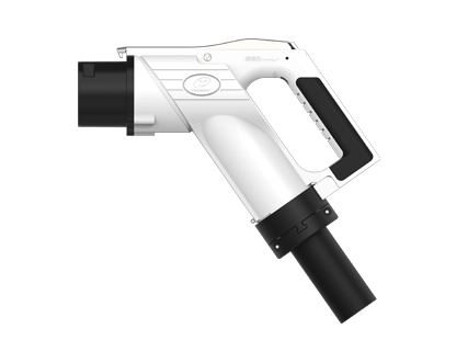
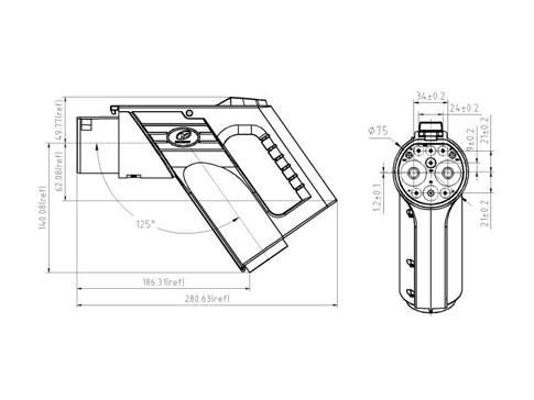
Model details of YG 762 DC vehicle connector (this specification applies to the model in the following table): | |||||||||||
No. | Name | Port wiring specification (mm²) | |||||||||
DC+ | DC- | PE | A+ | A- | CC1 | CC2 | S+ | S- | |||
1 | The YGC762-EV-P9P-80 plug | 20 | 20 | 25 | 4 | 4 | 0.75 | 0.75 | 0.75 | 0.75 | |
2 | The YGC762-EV-P9P-125 plug | 35 | 35 | 25 | 4 | 4 | 0.75 | 0.75 | 0.75 | 0.75 | |
3 | The YGC762-EV-P9P-160 plug | 50 | 50 | 25 | 4 | 4 | 0.75 | 0.75 | 0.75 | 0.75 | |
4 | The YGC762-EV-P9P-200 plug | 70 | 70 | 25 | 4 | 4 | 0.75 | 0.75 | 0.75 | 0.75 | |
5 | YGC762-EV-P9P-250 plug | 80 | 80 | 25 | 4 | 4 | 0.75 | 0.75 | 0.75 | 0.75 | |
6 | The YGC762A-EV-P9P-125 plug | 35 | 35 | 25 | 4 | 4 | 0.75 | 0.75 | 0.75 | 0.75 | |
7 | The YGC762A-EV-P9P-160 plug | 50 | 50 | 25 | 4 | 4 | 0.75 | 0.75 | 0.75 | 0.75 | |
8 | The YGC762A-EV-P9P-200 plug | 70 | 70 | 25 | 4 | 4 | 0.75 | 0.75 | 0.75 | 0.75 | |
9 | YGC762A-EV-P9P-250 plug (250A ultrasound) | 70 | 70 | 25 | 4 | 4 | 0.75 | 0.75 | 0.75 | 0.75 | |
10 | The YGC762A-EV-P9P-250 plug | 80 | 80 | 25 | 4 | 4 | 0.75 | 0.75 | 0.75 | 0.75 | |
Adapt cable | |||||||||||
No. | Specifi cations | Adapt cable specifications | Number of cable core | OD (mm) | |||||||
1 | 80A | TPE 2x20mm2+25mm2+2x4mm2+2xP(2x0.75mm2)+P(6x0.75mm2) | 15 | Φ 32±1 | |||||||
2 | 125A | TPE 2x 35mm2+25mm2+2x4mm2+2xP(2x0.75mm2)+P(6x0.75mm2) | 15 | Φ 36±1 | |||||||
3 | 160A | TPE 2x50mm2+25mm2+2x4mm2+2xP(2x0.75mm2)+P(6x0.75mm2) | 15 | Φ 36.5±1 | |||||||
4 | 200A | TPE 2x70mm2+25mm2+2x4mm2+2xP(2x0.75mm2)+P(6x0.75mm2) | 15 | Φ 40±1 | |||||||
5 | 250A | TPE 2x 80mm2+25mm2+2x4mm2+2xP(2x0.75mm2)+P(6x0.75mm2) | 15 | Φ 40±1 | |||||||
6 | 80A | TPE 2x20mm2+25mm2+2x4mm2+2xP(2x0.75mm2)+P(7x0.75mm2) | 16 | Φ 32±1 | |||||||
7 | 125A | TPE 2x 35mm2+25mm2+2x4mm2+2xP(2x0.75mm2)+P(7x0.75mm2) | 16 | Φ 36±1 | |||||||
8 | 160A | TPE 2x50mm2+25mm2+2x4mm2+2xP(2x0.75mm2)+P(7x0.75mm2) | 16 | Φ 36.5±1 | |||||||
9 | 200A | TPE 2x70mm2+25mm2+2x4mm2+2xP(2x0.75mm2)+P(7x0.75mm2) | 16 | Φ 40±1 | |||||||
10 | 250A (Ultrasonic welding) | TPE 2x 70mm2+25mm2+2x4mm2+2xP(2x0.75mm2)+P(7x0.75mm2) | 16 | Φ 40±1 | |||||||
11 | 250A | TPE 2x 80mm2+25mm2+2x4mm2+2xP(2x0.75mm2)+P(7x0.75mm2) | 16 | Φ 40±1 | |||||||
Attention | |||||||||||
★ The above is the general product model, wiring, please choose according to the line diameter requirements, if there is any customized requirements, please consult our company; ★ Cable harness for customized products need to be specific models according to the actual application, consult our company for details. | |||||||||||
Electrical parameters | Port definition | DC± | PE | A± | CC1 | CC2 | S± | ||||
Wiring specification (unit: mm2) | 25 | 35 | 70 | 70 | 80 | 25 | 0.75~ 4 | 0.75 | 0.75 | 0.75 | |
Contact Terminal Diameter (mm) | Φ12 | Φ6 | Φ3 | Φ3 | Φ3 | Φ3 | |||||
Rated Operating Voltage (DC) | 750V/1000V | / | 0~30V | 0~30V | 0~30V | 0~30V | |||||
Rated Operating Current (DC) | 80A | 125A | 200A | 250A | 250A | / | 2~20A | 2A | 2A | 2A | |
Contact Resistance | ≤0.3mΩ | ≤0.4mΩ | ≤3mΩ | ||||||||
Insulation Resistance | ≥2000MΩ(1000V AC) | ||||||||||
Pressure withstand (50Hz, AC normal) | Test after plug wiring: ① Resistance voltage between DC + and DC-3500V AC 1min; ② DC +, DC-and PE, S +, S +, A +, A-resistance voltage 1500V AC 1min; ③ PE and S +, S-, A +, A-respectively resistant voltage 1500V AC 1min; ④ S +, S-, CC1, A +, A-two resistance voltage of 1500V AC 1min; Test after the socket is wired: ① Resistance voltage between DC + and DC-3500V AC 1min; ② DC +, DC-and PE, S +, S-, CC1, CC2, A +, A-resistance voltage 1500V AC 1min; ③ PE and S +, S-, CC2, A +, A-resistance voltage 1500V AC 1min; ④ S +, S-, CC2, CC1, A +, A-two mutual voltage resistance of 1500V AC 1min | ||||||||||
Mechanical performance parameters | Service life: | 10000 times | |||||||||
| Insertion force: | <140N | ||||||||||
| Lock-in force: | 200N | ||||||||||
Environmental performance parameters | Before insertion: | YG 762 / YG762A IP54; | |||||||||
| After insertion: | YG 762 / YG762A IP55; YG762A The electrical part can reach IP67 (except the connection interface with the socket). | ||||||||||
| Note: | Avoid the tail wiring bending radius <6 cable OD | ||||||||||
| Ambient temperature: | -30℃ ~ + 50℃ | ||||||||||
Material | Enclosure: | Engineering plastics (high-performance PC) | |||||||||
| Terminal: | copper, surface plated silver / nickel | ||||||||||
| Seal parts: | silicone rubber or elastic insulation material | ||||||||||
| Flame-retardant grade: | UL94 V-0 | ||||||||||
Implementation standards | GB / T 18487.1-2015 EVs-Part 1: | General Requirements | |||||||||
| GB / T 20234.1-2015 Connecdevices for conductive charging of electric vehicles-Part 1: | General Requirements | ||||||||||
| GB / T 20234.3-2015 Connections for EV Transmission Charging; Part 3: | DC Charging Interface | ||||||||||
Electrical principle | Function definition of each terminal: | ||||||||||
No. | Terminal identification | Function definition | |||||||||
| 1 | DC+ | The DC power supply is positive, and the DC power supply is connected to the battery cathode | |||||||||
| 2 | DC- | The DC power is negative, connect the DC power is negative and the battery is negative | |||||||||
| 3 | PE | Protective ground (PE), connect to the ground wire of the power supply equipment and the vehicle body ground wire | |||||||||
| 4 | S+ | Charging communication CAN _ H, connecting the communication line between non-on-board charger and electric vehicle | |||||||||
| 5 | S- | Charging communication CAN _ L, connecting the communication line between the non-on-board charger and the electric vehicle | |||||||||
| 6 | CC1 | Charging connection confirmation 1 | |||||||||
| 7 | CC2 | Charging connection confirmation 2 | |||||||||
| 8 | A+ | The low-voltage auxiliary power supply is connected to the low-voltage auxiliary power supply provided by the non-on-board charger for electric vehicles | |||||||||
| 9 | A- | Low voltage auxiliary power supply is negative, connected to the low voltage auxiliary power supply provided by non-on-board charger for electric vehicles | |||||||||
| 10 | T1+ | The temperature sensor is positive on the right side of the DC power supply | |||||||||
| 11 | T1- | The temperature sensor of the DC side is negative | |||||||||
| 12 | T2+ | The negative-side temperature sensor of the DC power supply is positive | |||||||||
| 13 | T2- | The temperature sensor is negative on the negative side | |||||||||
★ T1-and T2-are available | |||||||||||
| 14 | Electronic lock at 12V | The electronic lock in the vehicle connector is positive | |||||||||
| 15 | electronic lock GND | The electronic lock inside the vehicle connector | |||||||||
| 16 | Electronic lock feedback SIGN + | The electronic lock in the vehicle connector works (unlock / lock) and the feedback is positive | |||||||||
| 17 | Electronic lock feedback SIGN- | The electronic lock in the vehicle connector works (unlock / lock) and the feedback is negative | |||||||||
★ Electronic lock GND and electronic lock feedback SIGN-availabl | |||||||||||
Accessories for vehicle connector | 1. YG762 Plug protection cover assembly (optional): | ||||||||||
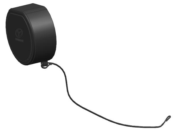 | |||||||||||
★ Model: YG 762-01-02-00 (112980000706) to order according to the demand, the order ratio is 1:1 (plug: YG 762 plug protection cover assembly). | |||||||||||
2. YG 762 Electromagnetic lock assembly (required): | |||||||||||
YG 762 (normally open and normally closed) YG 762-01-01-00 (112980000700 closed) YG 762-01-01-00 / 01 (112980001628 regular open) | Y G762A Electronic gun lock (normally open and normally closed) 501021703907 (Motor electronic lock) 501021703906 (Motor motor lock) | ||||||||||
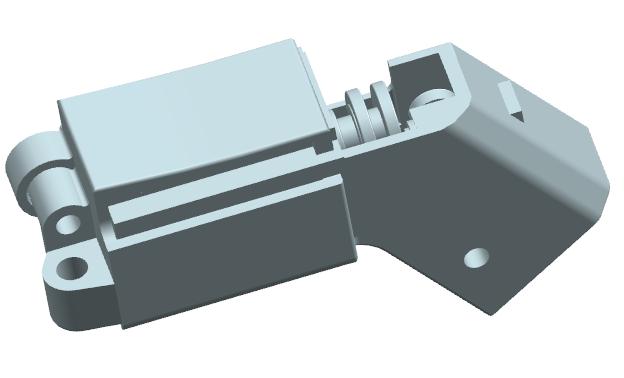 | 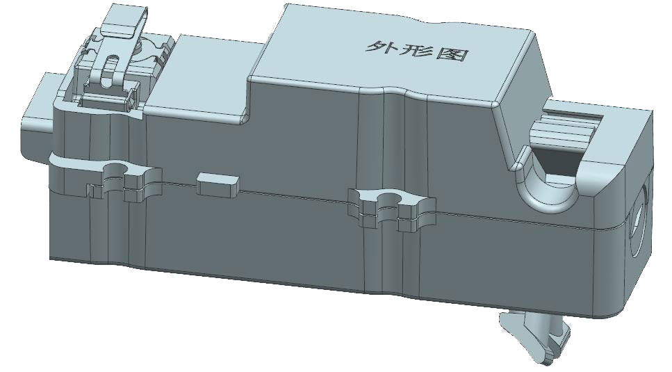 | ||||||||||
★ Model: order according to the demand, order ratio 1:1 (plug: electromagnetic lock component). | |||||||||||
3. PCBA control board assembly (optional): | |||||||||||
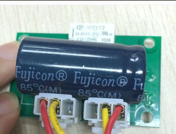 | |||||||||||
★ Model: order according to demand, order ratio 1:1 (plug: PCBA control board assembly) YG762-01-12-00(112980001149)0.4M YG762-01-12-00/01(112980002602)1.5M YG762-01-12-00/02(111009802061)1.5M Band terminal | |||||||||||
4. Temperature sensor (required): | |||||||||||
| A) Temperature sensor PT1000 (Φ 3.010mm) (501021701034) Size resistance table:
Temperature correction factor: 7℃ (actual temperature of the terminal = sensor temperature + 7℃) | |||||||||||
B) Temperature sensor NTC 10K 3950 (501021702315) dimensional resistance table:
Temperature correction factor: 7℃ (actual temperature of the terminal = sensor temperature + 7℃) | |||||||||||
C) NTC 3435 10KΩ (501021701772) | |||||||||||
D) Temperature switch (90 ± 5℃ off) (501021701036) Resistance table | |||||||||||
E) Temperature Switch (100 ± 5℃ off) (501021702297) | |||||||||||
★ The plug selects two sensors or temperature switches in DC + / DC-according to the standard. | |||||||||||
5. Empty seat (optional): | |||||||||||
YG349-02-00-00KR |
YG762-50-00-00KR | ||||||||||
★ Model: YG 349-02-00-00 KR (112980000394) YG 762-50-00-00 KR (111000500836) ★ Choose according to the demand, and match the plug order, order ratio 1:1 (plug: empty seat) ★ According to the demand, the tail line can be connected to the connector; | |||||||||||
6. YG762A. Simple emergency unlocking lever (optional): | |||||||||||
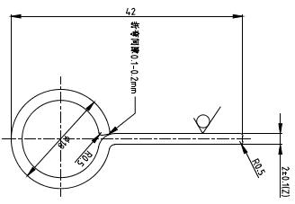 | |||||||||||
★ Model: YG762 Simple Emergency Unlocking Rod (114039803419) ★ According to the demand, and order with the plug, a charging pile site according to the actual situation. | |||||||||||
Announcement information | explain: ★ The announcement logo corresponds to the model table "name" ★ Note: there is no announcement of the plug-type socket, our company will increase according to the actual situation | ||||||||||
Announcement logo | temperature control device | Electromag netic lock device | Strong inspection report number | CQC report number | |||||||
YGC762-EV-P9P-80 | have | have | QA16EE1EB4141 QA16EG1EB4141 | QA16XX1EFC341 | |||||||
YGC762-EV-P9P-125 | have | have | QA16EE1EB4141 QA16EG1EB4141 | QA16XX1EFC341 | |||||||
YGC762-EV-P9P-200 | have | have | QA16EE1EB4141 QA16EG1EB4141 | QA16XX1EFC341 | |||||||
YGC762-EV-P9P-250 | have | have | QA16EE1EB4141 QA16EG1EB4141 | QA16XX1EFC341 | |||||||
YGC762A-EV-P9P-80 | have | have | QA18EE1XZ5471 | C QC20029252191 | |||||||
YGC762A-EV-P9P-125 | have | have | QA18EE1XZ5471 | C QC20029252191 | |||||||
YGC762A-EV-P9P-200 | have | have | QA18EE1XZ5471 | C QC20029252191 | |||||||
YGC762A-EV-P9P-250 | have | have | QA18EE1XZ5471 | C QC20029252191 | |||||||
Prohibit exposure of YG 762 products to rain water environment.
When using the charging socket:
(1) When the vehicle connector is inserted and stuck, check whether there is any foreign body drilling in the socket hole. If there is no foreign body after inspection
Method Normal plug and pull, contact the manufacturer for processing;
(2) When reporting the insulation fault, first ensure that the battery service switch is disconnected, and close the main gate of the car body circuit system when necessary,
Check whether the socket is leaking, if there is water leakage, first wipe, with a multimeter to detect the insulation between the terminals
Resistance (except between PE and CC1), the resistance value of 2000M Ω is normal, otherwise contact the manufacturer for treatment;
(3) In case of abnormal charging connection, make sure that the battery service switch is in an disconnected state and close the body circuit system if necessary
For the total gate, detect the resistance value between PE and CC1, if the resistance value is 1000 + / -30 Ω is normal, otherwise contact
Manufacturer processing;
(4) Regularly wipe and clean the charging interface with alcohol, especially the metal jack inside the socket.

Tailoring connectors to your unique needs.
Provide systemic solutions
Respond to needs within 12 hours