𐄀 Technology Connection to Future
Specifications | ||
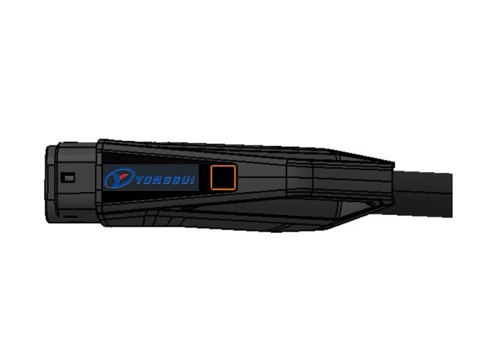
Product name | European standard DC charging gun | |
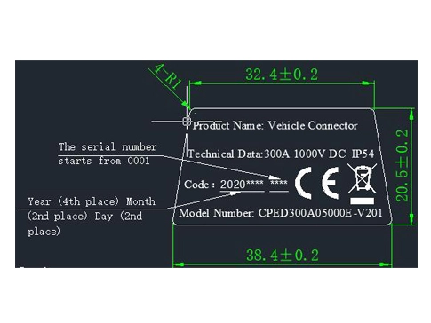
Model number | CPED300A****E-V2xx (...Indicates rated current, * * * * indicates cable length, xx represents the serial number) | |
Rated voltage | DC1000V | |
Rated current | Power line: 300A signal line: 2A | |
Number of terminals | Power wire: 2 ground wire: 1 signal wire: 2 | |
Applicable standards | • IEC 62196.1-2014 Plugs, socket-outlets, vehicle connectors and vehicle inlets – Conductive charging f electric vehicles - Part 1: General requirements • IEC 62196.3-2014 Plugs, socket-outlets, vehicle connectors and vehicle inlets - Conductive charging of electric vehicles –Part 3: Dimensional compatibility and interchangeability requirements for d.c. and a.c./d.c. pin and contact-tube vehicle couplers • IEC 61851.1-2001 Electric vehicle conductive charging system - Part 1: General requirements • IEC 60309.1-2012 plugs, socket-outlets and couplers for industrial purposes - Part 1: General requirements | |
Operating Ambient temperature range | ﹣35~+50℃ Both use under condensation and freeze is prohibited. | |
Degree of protection | IP44 | |
Dimension | Charging gun | (L) 274 * (W) 74 * (H) 175 (mm) |
Cable | Length according to customer requirements | |
Note: This product meets the requirements of RoHS 2.0+REACH.
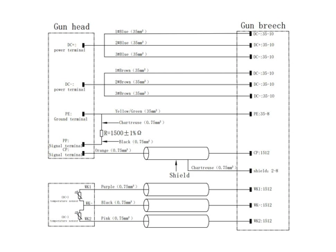
Cable core wire function allocation table | ||||||
| Core function allocation | ||||||
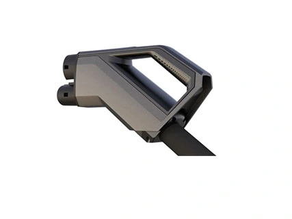
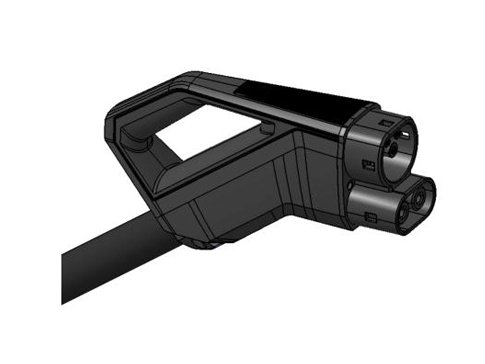
Front view of charging gun head |
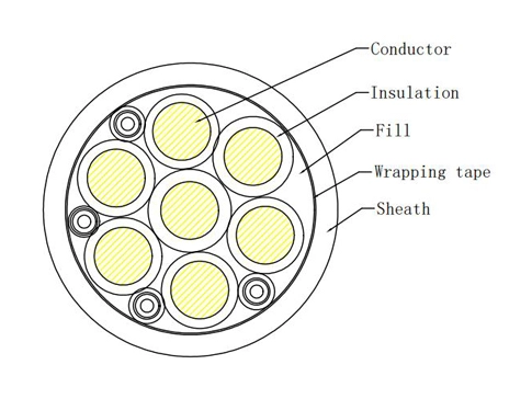
Cable cross section |
Resistance wiring diagram (The resistance 3 # line is connected the 3 # ground wire, and the resistance 4 # is connected to the PP signal terminal) | ||||
Core number | Core color | Terminal | Sectional area of core conductor (mm2) | |||
300A | ||||||
1 | Brown | DC+ | 3x35 | |||
2 | Blue | DC- | 3x35 | |||
3 | Yellow / Green | PE + Resistance lead | 35 | |||
4 | Black | PP (Resistance lead) | 0.75 | |||
5 | Orange | CP | 0.75 | |||
6 | Violet | WK1+ |
(The negative lines oftemperature sensors WK1 and WK2 are connected to line 8 #) | |||
7 | Pink | WK2+ | ||||
| 8 | Black | WK- | ||||
The main components | ||||
Serial number | Part name | Material | surface treatment | Remarks |
1 | Charging gun shell | PBT+PC | - | Color: Cold gray |
2 | Charging gun head | PA66+GF25 | - | Color: Black |
3 | Ground terminal | Brass + red copper | silver | - |
4 | Signal terminal | brass | silver | - |
5 | Power terminal | Brass + red copper | silver | 300A |
Brass | silver | |||
6 | Sealing ring (inside the housing) | Silica gel | - | - |
7 | Cable snap ring (inside the housing) | Aluminum alloy | anodic oxidation | - |
8 | Resistance (inside the housing) | - | - | - |
9 | Temperature sensor (inside the housing) | - | - | - |
10 | Electric vehicle cable | TPU (outer sheath) | - | - |
1) Charging gun shell Consists of high-incombustibility, -insulation and – weather resistance resin materials, PBT+PC (UL94-V-0). 2) Charging gun head Composed of high incombustibility, insulation and wear resistance nylon plus glass fiber material, PA66 + GF25 (UL94- V-0) 3) Ground terminal, Power terminal Composed of brass alloy and pure copper, the whole terminal is silver plated, T2 or H62. 4) Power terminal (300A) It is composed of a stainless steel sleeve that wraps the jack end of the high-conductivity copper material, and then cooperates with the crimping end of the pure copper material. The entire terminal is silver-plated, T2. 5) Signal terminal Composed of brass material, the terminal is silver plated, H62. 6) Sealing ring Composed of high incombustibility, insulation and weather resistance silicone material 7) Cable snap ring The cable snap ring suitable for 300A cable is forged by aluminum alloy material; 8) Resistance Resistance R=1500 ± 1% Ω. 9) Temperature sensor Model: PT1000, R0 ℃ = 1000Ω. 10) Electric vehicle cable The structure is shown in Table 3, 5 and figure 3. 10-1) Reference standard: • IEC 60228 Conductors of insulated cables • IEC 62893-1 Charging cables for electric vehicles for rated voltages up to and including 0,6/1 kV - Part 1: General Requirements • IEC 62893-2 Charging cables for electric vehicles for rated voltages up to and including 0,6/1 kV - Part 2: Test methods 10-2) technical requirements: (1) Rated voltage: 1000V; (2) Ambient temperature: - 40 ~ 90 ℃; (3) Conductor resistance (20 ℃): 35mm2≤0.554Ω/Km、0.75mm2≤26Ω/Km; (4) Main line: line-line insulation impedance: 1000V DC 15min ≥ 500m Ω; leakage current: 3500V DC 15min ≤ 5mA; (5) Bending radius of cable: ≤ 6D; (6) UV resistance: ISO 4892-3 (1000H, no discoloration, no cracking, tensile strength retention rate, elongation at break ≥80%); (7) Weather resistance, friction resistance, halogen-free, rocking test, low temperature impact test, meandering test, damp heat test, high and low temperature cycle test, anti-extrusion test, compatibility test, chemical liquid resistance and other tests refer to IEC60228 , IEC62893-1 and IEC62893-2. | ||||
Detailed parameters of electric vehicle cable | |||||
Explain | Unit | Cable specification | |||
300A | |||||
structure | DC line structure | Conductor | Specification structure | mm² | 3*35 |
Insulation | Colour | - | Brown, Blue | ||
PE line structure | Conductor | Specification structure | mm² | 1*35 | |
Insulation | Colour | - | Yellow / Green | ||
Signal line structure | Conductor | Specification structure | mm² | (4*0.75)P | |
Insulation | Colour | - | Black, Orange, Purple, Pink | ||
Outer sheath | Texture of material | - | TPU | ||
External diameter | mm | 37.5±0.05 | |||
Colour | - | black | |||
Table a: Test Items with IEC Standards | |
Reference standard | Items |
IEC62196-1 15 | Resistance to ageing of rubber and thermoplastic material. |
IEC62196-1 20 | IP degree and humidity |
IEC62196-1 21 | Insulation resistance and dielectric strength. |
IEC62196-1 23 | Normal operation |
IEC62196-1 24 | Temperature rise |
IEC62196-1 25 | Pull force on cord anchorage |
IEC62196-1 26 | 2. Impact blow test, 3. Drop test, 4. Flexing test, |
IEC62196-1 27 | Torque test on screws or nuts |
IEC62196-1 29 | Resistance to heat, fire and tracking |
IEC62196-1 30 | Corrosion and resistance to rusting |
IEC62196-1 31 | Conditional short-circuit current withstand test |
Table B: test items and criteria | ||
Items | Decision criteria | |
1 | Appearance | The accessible surface of the charging gun should be free of burrs, flashes and similar sharp edges; the casing of the charging gun should be marked with the manufacturer's name or trademark, product model, rated voltage and rated current, etc. |
2 | Dimension | The external dimensions of the charging gun meet the requirements of the IEC62196-3 standard |
3 | Temperature rise | The maximum allowable temperature rise of the terminal should not exceed 50K |
4 | Insulation resistance | > 10MΩ (Applied voltage: 500V DC, 1 minute) |
5 | Withstand voltage | 3500V AC Leakage current ≤10mA, no breakdown or flashover in 1 minute |
6 | Charge gun insertion/withdrawal force | < 100N |
7 | Cable retention force | The cable must not fall out of the charging gun case. |
8 | Drop test | The specimen shall not be damaged and there shall be no separation or fall off of any parts in the gun shell |
9 | Vehicle drive over test | The specimen shall not be damaged and there shall be no separation or fall off of any parts in the gun shell |
10 | Service life test | Conduct no-load live plugging 10000 times, during the test, there shall be no continuous flash arc, after the test, there shall be no: 1. Deterioration without shell or partition; 2. No electrical connection or mechanical connection is loose; 3. Keep the continuity of signal transmission between contacts; 4. There shall be no flashover or breakdown during dielectric strength test (voltage reduced by 500V); |
11 | Protection level | Internal protection of gun shell IP67 |
12 | High temperature resistance test | The sample is not damaged and can be used normally (check the sample after returning to room temperature.) |
13 | Low temperature resistance test | The sample is not damaged and can be used normally (check the sample after returning to room temperature.) |
Table C: Test Method | ||
Items | Test Method | |
1 | Appearance | Check the surface condition visually and manually. |
2 | Dimension | Matching test |
3 | Temperature rise | Supply current according to product specification, measure the temperature of the following points. Test point: - DC terminal contact point surface -Shell surface |
4 | Insulation resistance | Insulation resistance tester plus 500V DC voltage to measure the insulation resistance between adjacent terminals and between each terminal and the shell |
5 | Withstand voltage | Apply 3500V AC voltage between adjacent power terminals and between power terminals and housing for 1 minute |
6 | Charge gun insertion/withdrawal force | When the vehicle charging base is fixed, measure the insertion / pull-out force of the charging gun head at the specified speed (excluding the insertion / pull-out force of the rubber seal of the vehicle charging base). |
7 | Cable retention force | In charging gun fixed condition, apply 753±1 N×120s to cable out direction from charging gun. |
8 | Drop test | Lift the test sample to a predetermined height, and then let it fall freely according to the predetermined state and collide with the impact table. |
9 | Vehicle drive over test | Roll over the connector which is placed naturally on concrete floor with the wheel of 2t vehicle. |
10 | Service life test | 10,000 times of no-load live plugging and unplugging. |
11 | Protection level |
select a swing tube of appropriate radius so that the height of the sample table is at the diameter of the swing tube, place the sample on the sample table so that the distance from the top of the sample to the sample spout is not more than 200mm, the sample table Does not rotate.
The water flow is calculated according to the number of spray holes of the pendulum tube, and each hole is 0.07 L / min. When spraying water, spray water from the spray holes in the 90 ° arcs on both sides of the midpoint of the pendulum tube to the sample. The test sample is placed in the center of the semicircle of the pendulum tube. The swing tube swings 180 ° on both sides of the vertical line for a total of 360 °. Each swing (2 × 360 °) is about 12s.
continuous watering for 10 min. |
12 | High temperature resistance test | Put the charging gun in the thermostat (105 ℃ × 1000 hours). |
13 | Low temperature resistance test | Put the charging gun in the thermostat (- 35 ℃ × 120 hours). |

Tailoring connectors to your unique needs.
Provide systemic solutions
Respond to needs within 12 hours